
A robotic welding arm can repeat a programmed path with high consistency, but structural parts rarely arrive in exactly the same position every time. 3D laser seam detection solves that problem by locating the joint before the arc starts and converting the measured geometry into a welding path.
Why Fixed Taught Paths Miss Real Joints
Inside-corner and fillet seams are common where a beam web meets a flange or where a stiffener joins a web. They are demanding to automate because torch access is restricted, cutting and assembly tolerances move the joint, and a single member may contain many welds in different positions.
A robot following a fixed taught path assumes that the production part sits exactly where the original teaching part sat. When fit-up, tack location or distortion moves the seam by a few millimeters, the torch can follow the programmed line while missing the actual joint. Scanning removes that assumption.
How 3D Laser Seam Detection Works
- A laser line is projected onto the part. When it crosses a corner or edge, the line bends with the surface geometry.
- A camera reads the laser profile. The changing line shape reveals the local surface profile; motion along the part builds a three-dimensional representation.
- Software identifies the joint. It recognizes the corner geometry and determines the seam’s start, end and direction.
- The position is transformed into robot coordinates. A calibrated relationship between sensor and robot tells the arm where to place and orient the torch.
- A welding path is generated and reviewed. The path and process parameters are checked before execution.
How DONSIN RA Uses Teach-Free Scanning
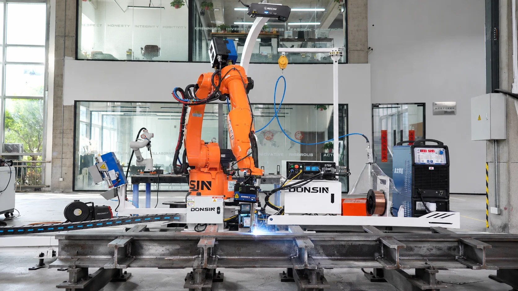
The DONSIN RA series teachless industrial welding system identifies the workpiece, detects seams and generates welding paths automatically. It is intended for large structural components containing many welds, where manual teaching can take longer than the welding itself.
The RA platform combines the scanning system with a track-mounted robotic welding arm. The reference configuration includes a 2,014 mm arm reach, 6 kg payload and 500 A welding source. Track travel and optional cantilever axes extend the working envelope so the robot can cover multiple zones on a long member without repeatedly lifting and repositioning the workpiece.
- Load and support the beam or column.
- Scan the workpiece with the 3D laser sensor.
- Detect the seams and generate proposed welding paths.
- Review the paths, torch orientations and process parameters.
- Weld zone by zone as the robot travels along the track.
What Scanning Can—and Cannot—Correct
| Condition | What the system can do | What the fabricator must control |
|---|---|---|
| Normal position variation | Locate the measured seam and adapt the robot path | Present the member within the system’s scanning and reach envelope |
| Changing stiffener locations | Detect repeated joint geometry at different positions | Confirm joint type and welding procedure |
| Poor fit-up or excessive gaps | Measure the joint location and visible geometry | Keep gaps and alignment within the approved welding procedure |
| Scale, rust, oil or contamination | Scanning may still identify visible geometry in suitable conditions | Prepare the surface for reliable sensing and weld quality |
| Blocked line of sight | Scan only surfaces reached by the projected laser and camera | Review deep channels, enclosed sections and access with the supplier |
Practical Limits to Discuss Before Purchase
- Fit-up remains fundamental. A sensor can locate a gap but cannot make an unacceptable joint weldable.
- Surface condition matters. Heavy rust, scale, oil, smoke and spatter can affect sensing and welding quality.
- Optics require protection. Plan sensor shielding, air cleaning where appropriate and routine inspection of optical surfaces.
- Geometry must remain visible. Deep enclosed corners and box sections may need a different access or scanning strategy.
- Joint scope must be confirmed. The RA series is primarily intended for fillet welds on light steel structures such as H-section columns, roof beams and crane beams, especially open members.
Preparation Checklist for Reliable Teachless Welding
- Tack parts consistently so they do not move during welding
- Keep the joint area clear of heavy contamination
- Define parameters for each joint type, material and weld size
- Verify parameters on a representative test piece
- Maintain calibration records and recalibrate after collisions or hardware changes
- Run a trial using your own beams before finalizing the system
When Teachless Scanning Creates the Most Value
The greatest benefit appears in high-mix structural production: columns, roof beams and crane beams that share common joint types but differ in stiffener positions, lengths and details. In this environment, the main saving is programming time. If the same rigidly fixtured part is welded thousands of times, a conventional taught path may already be sufficient.
To compare RA-S7, S7Pro, S8 and S8Pro configurations, read our guide to teachless robotic welding for H-beams and steel structures. If your parts are smaller and better suited to collaborative arc welding, see how to choose a DONSIN RW welding cobot.
Information to Provide for an Application Review
- Drawings of typical beams, columns and connection details
- Section sizes, lengths and weights
- Material grade, weld leg size and joint type
- Sample parts or clear photographs of the target seams
- Workshop dimensions, crane capacity and material flow
Evaluate 3D Seam Detection on Your Parts
Send DONSIN your structural drawings and joint photographs. Our engineers can review seam visibility, robot coverage and the appropriate RA configuration.
Request a Teachless Welding Review


